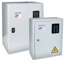
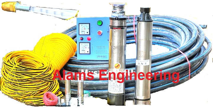
Supply:Pumps, Filter/ Strainer/ Screen, Control Box & Cables
GENERAL CATALOGUE
EU REGULATION N. 547/2012
Pumps with a minimum efficiency index MEI ≥ 40 in conformity with the EU Regulation in force from 1st January 2015.
The bench mark for the most efficient water pumps is MEI ≥ 70.
The efficiency of a pump with a trimmed impeller is usually lower than that of a pump with a full diameter The trimming of the impeller adapts the pump to a fixed duty point, resulting in a lower energy consumption. The minimum efficiency index (MEI) is based on the full diameter impeller.
The functioning of the water pump with variable places of operation can be more efficient and economical if, for example, it is controlled by means of a variable speed motor which adjusts the function of the pump to the System.
GUARANTEE
All Pumps are generally guaranteed for a minimum of 01 year subject to the terms and conditions of as long as any necessary spare parts fitted during the period of guarantee are original spare parts.
Centrifugal Pump-set,
Submersible Pump-set,
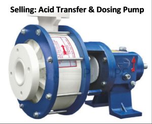
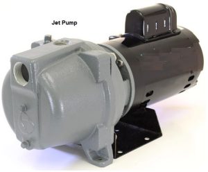
Acid Transfer & Dosing Pump-set and Jet Pump-set,
Booster Pump-set etc.
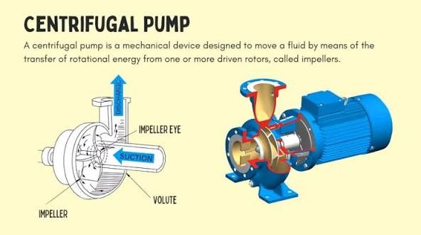
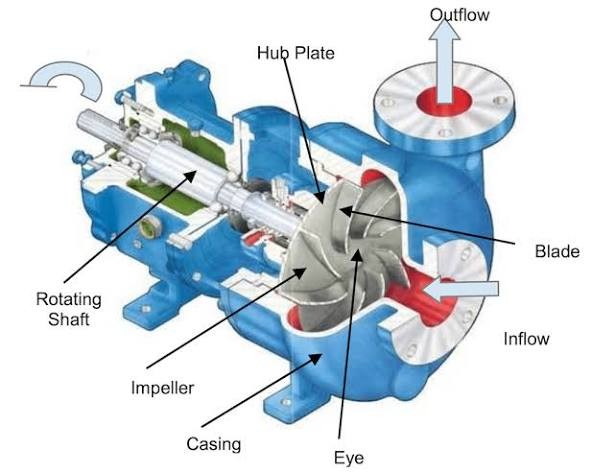
The operation of a centrifugal pump is based on the principle of centrifugal force:
Suction: A motor rotates the impeller at high speed, creating a low-pressure zone, or partial vacuum, at the center (eye) of the impeller.
Acceleration: The rotating impeller’s curved vanes catch the fluid and accelerate it tangentially and adially outward, significantly increasing its velocity and kinetic energy.
Pressure Conversion: This casing is designed with a gradually expanding cross-sectional area, which slows the fluid’s velocity and converts its high kinetic energy into static pressure energy.
Discharge: The pressurized fluid is forced out through the piping system.
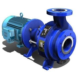
Main Components
The primary components of a centrifugal pump include:
Impeller: A curved vanes that imparts energy to the fluid.
Casing: Encloses the impeller.
Shaft: Transmitting the rotational power.
Motor/Driver: Provides the mechanical energy to rotate the shaft and impeller.
Bearings: Support the rotating shaft,
Sealing System: Prevents the pumped fluid from leaking.
Applications
Municipal Water Suppl,
Agriculture, Irrigation, Sprinkler systems,
Industrial Water Supply,
Mining Industry,
Pressure Boosting,
Ground Water Lowering,
HVAC Systems
N.B.: our all pumps compatible with Auto/PLC/ Telemetry (GSM)/SCADA Systems and Panel: Star Delta, DOL, ATS.
ACID TRANSFER & DOSING PUMP AND JET PUMP
Origin: Germany & Italy
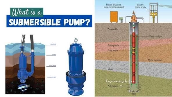
Supply:Submersible Pumps
A submersible pump is a type of pump that is designed to be fully immersed in the fluid it is pumping.
Key Characteristics and Working Principle
Submerged Operation: Operate underwater, often at the source of the fluid.
“Push” Mechanism: A submersible pump pushes the fluid toward the surface.
Cooling and Lubrication: Naturally cools the sealed motor and lubricates moving parts,
Reduced Cavitation: Being submerged also prevents cavitation,
Quiet Operation: The water surrounding the pump muffles the sound of the motor,
Common Applications
Water Wells: Extracting groundwater.
Wastewater Management: Moving sewage, effluent, and sludge,
Dewatering: Removing accumulated water from construction sites,
Oil and Gas Industry: High-powered Electric Submersible Pumps (ESPs) are used to lift crude oil,
Irrigation: Drawing water for agricultural use.
Fountains and Ponds: Used in decorative water features for circulation and filtration.
Design Features
Extensive range of sizes (from 6 to 12 inches) enables precise pump selection in accordance with operating conditions. That will increase reliability and efficiency of operation,
Rated voltage: 50Hz, 3-phase, 380/400 V,
Rotation speed: 3000 rpm,
motor power: up to 130 kW,
Head range: up to 550 m,
Capacity range: 5 – 290 m3/h,
Rotation speed: 3000 rpm
Operation Condition
Pumped liquid: Clear fluid/water,
Liquid temperature: up to 25 °С
Total dissolved solids (TDS): up to 1500 mg/l
Diameter range (inches): 6, 8, 10, 12
Sand: up to 100 mg/l
The few pumps are covered with a three 06 month to 03 year warranty. Estimated operation lifetime is 4-10 years provided that the pump is operated accordingly, to the operation manual and the pump consists of a single manufacturer’s recommendations or multistage single-entry pump and a rigidly coupled rewindable water-filled electric motor. The pumps have been engineered in accordance with modern requirements to efficiency and reliability: taking into account heavy duty operation conditions and unstable power supply quality.
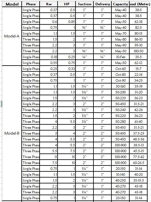
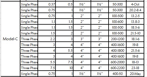
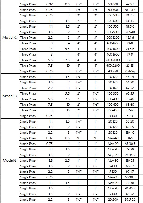
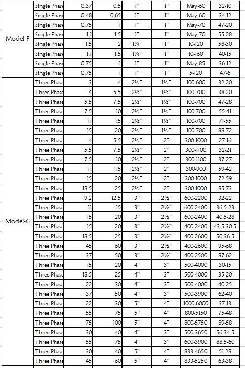
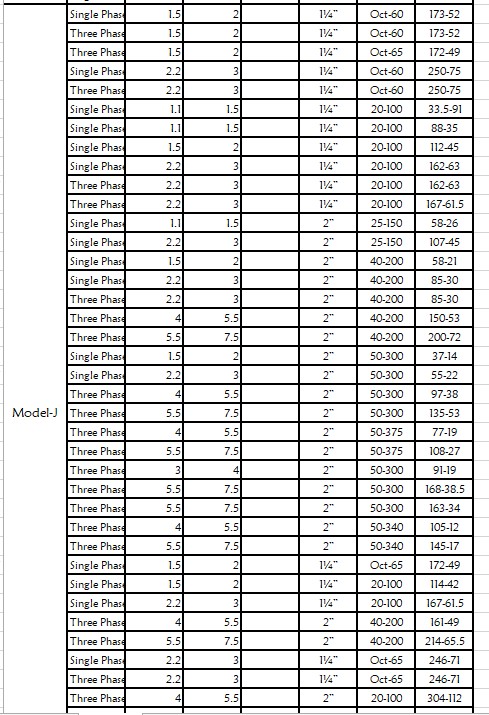
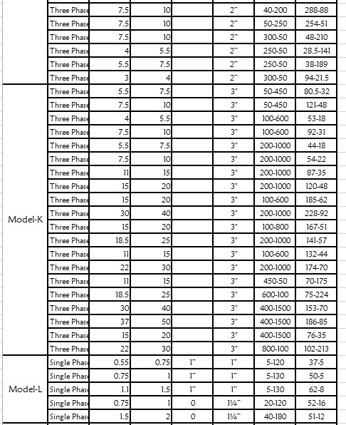
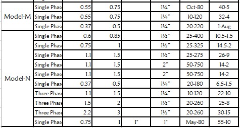
Available Pumps (Model) is as follows:
Pump Selection and Operation Guideline
Main Parameters
The information in this section provides the recommendations on selection, installation and operation of the submersible pumps in the most efficient way, avoiding the most typical mistakes and significantly reducing the number of failures.
The water supply system consists of many elements and the main of them are the pumps, pipes, valves, tanks and reservoirs. Each element influences on others.
Q-H curve to show head vs. capacity relation,
Q-P curve: power vs. capacity relationship for multistage pumps the curve can be shown for one stage or whole pump,
Efficiency curve to show stage efficiency with taking into account losses in non-return valve and at the pump inlet
Pump Selection Sequence
Required capacity and head values,
Well (borehole) data or ones got by measurement:
Internal well diameter,
Static water level,
Well yield (or output),
Dynamic water level (pumping water level) to correspond with well yield,
Well screen/filter depth,
Chemical composition and solids content of liquid/water,
1st stage. Determining the pump diameter,
2nd stage. Determining the pump capacity,
3rd stage. Determining required pump head,
Static Head of System Characteristic
static part is determined by geometric height of water lift relative to dynamic water level and geometric height of the tank.
Dynamic Head of System Characteristic
Dynamic head is determined by losses in the pipeline and takes the form of quadratic dependence: hf (Q) = k·Q2
k – loss coefficient that depends on losses along the pipeline and elements resistances (valves, manifolds, valves, adapters, etc.). That relation is shown as parabola on chart
Pump Installation Requirement
If the required pump capacity is higher than the borehole (well) yield then a dry running sensor shall be applied.
Possible well defects such as
pipe misalignment,
poor quality of weld,
well curvature
may make the pump installation difficult or even impossible. The motor bottom level must be at least 1 m above the well filter. Failure to do so carries the risk of large amount of sand ingress and increased wear of the pump.
Discharge pipe diameter shall be equal to discharge nozzle diameter or differ insignificantly. In selecting discharge pipe diameter the liquid flow-rate shall remain within 1.5 – 3.0 m/s.
1. Pipe selection of lower diameter
Use of pipes of lower diameter than size of discharge nozzle (thread or flanged) for saving purpose results in major loss due to friction and increase of required head.
2. Cable selection of smaller cross-section
Selecting cross-section lower than recommended will lead to significant voltage drop which would affect the motor and cause overheating.
3. Pump capacity exceeds well yield
That leads to dry running operation, which will cause:
motor overheating
rapid wear of bearings
increased corrosion
4. Poor quality of supply voltage and absence of control panels
Direct connection to the power supply does not help to protect the motor from the most typical causes of failure such as current unbalance, phase reversal, under/overvoltage, etc.
5. Built-in non-return valve dismantling
Instrumentation and sensors (water level, pressure, flow rate, voltage, current, number of starts/stops and time of pump operation, etc.) provide valid data on the pump operation and system features for monitoring and timely intervention into pump operation.
6. Absence of instrumentation
Instrumentation and sensors (water level, pressure, flow rate, voltage, current, number of starts/stops and time of pump operation, etc.) provide valid data on the pump operation and system features for monitoring and timely intervention into pump operation.
Pump Performance Curve and Dimensions
rated rotation speed
voltage supply frequency: 50 Hz
pumped liquid: clean fresh water
water temperature: +20°С
kinematic viscosity: 110-6m2/s (1cSt )
Performance curves are given for one pump stage as well as power curves.
Rewindable Submersible Motors
Motor is filled with a liquid allowing contact with potable water.
Motor storage temperature: -30…+60 °С (-22…140 F)
Lack of the liquid can be refilled with clean water (at storage tem above +4 °С)
Vertical and horizontal installation are equally possible (e.g. booster modules)
Flanges and shafts are made in accordance with appropriate NEMA standards
Resistance to unstable voltage
Casing made of AISI 316 stainless steel
Sand guard for mechanical seal protection from the solid particles
Rotor’s «squirrel cage» is made of copper for increased efficiency
High-temperature rewindable winding with PE2 insulation (up to 100 °С); temperature sensor is optionally available for overheating protection
Radial bearings of composite materials with spiral grooves for better lubrication
Heavy duty self-aligning water lubricated thrust bearing
Counter thrust bearing for the rotor upward movement prevention
Reliable mechanical seal the world’s leading manufacturers
Rubber diaphragm for the liquid expansion compensation
Brand Name
Pedrollo – Italy,
KSB – German (manufacturing in India/China),
Leo – China &
Gazi/RFL/Hatim – Bangladesh.
Certifications
Our Pumps comply with ISO 9001:2008. The equipment is manufactured in accordance with internationally recognized ISO, ANSI, DIN, ASME, ATEX and API standards and in accordance with the customer specifications as well.
Supply:Deep Tube Well Filter / Stainer / Screen
A deep tube well filter, often called a strainer is prevents sand, debris, and sediment from entering the pipe while allowing clean water to flow into the well. It’s typically a perforated or slotted stainless-steel/UPVC pipe at the well’s lower end, sometimes with a fine mesh screen, designed to work with specific geological conditions to ensure clean water extraction, protect the pump, and prolong the life of the well.
How it works
The filter is placed at the bottom of a deep tube well, positioned within an aquifer.
It allows water to flow in while blocking sand and other sediment into the well pipe.
This protects the pump from damage and keeps the water supply cleaner.
Key features
Material: Often made of stainless steel and also available in UPVC, C-D-E Class.
Design: perforated or slotted pipe, or mesh screen.
Placement: The length and location of the filter are determined by the location of the aquifer.
Slot Size of Screen
The correct slot size for a deep tube well filter depends on the aquifer’s sediment size, and common ranges are 0.1 mm to 3 mm. A careful selection balances sand exclusion with sufficient water entry and can be aided by a sieve analysis of the surrounding formation.
How to select the right slot size
Analyze the aquifer’s sediment: A sieve analysis to determine the average particle size and match slot size to sediment,
Fine sand: Use a smaller slot size, such as 0.1 mm to 0.75 mm.
Coarse sand and gravel: up to 3 mm.
Consider filtration efficiency: A smaller slot size is more precise but may reduce water flow. A larger slot size increases the open area, which can improve efficiency and reduce entrance velocity, minimizing sand pumping.
Choose a robust filter type: For deep or high-pressure wells, slotted or wedge wire screens are recommended for their strength and durability.
Different Sizes:
Common standard slot sizes include (in mm):
Fine: 0.1 mm, 0.15 mm, 0.2 mm, 0.25 mm
Medium: 0.3 mm, 0.4 mm, 0.5 mm, 0.6 mm, 0.7 mm, 0.8 mm
Display of pump parameters: input current, voltage, running time and number of starts
History of accidents: Dispatching signals: «Accident», «Station is on», «Pump is on», sensors
Programmable on/off regime for pumps
Group mode for several panels
Options
Overvoltage protection
Surge (lightning) protection
Temperature sensor for motor winding
Interference
Sensor condition
Current consumption
Voltage on each phase
Hours of operation
Number of starts
List of recent failures
Our Pumps comply with ISO 9001:2008. The equipment is manufactured in accordance with internationally recognized ISO, ANSI, DIN, ASME, ATEX and API standards and in accordance with the customer specifications as well.
Application
Municipal Water Suppl,
Agriculture, Irrigation, Sprinkler systems,
Industrial Water Supply,
Mining Industry,
Pressure Boosting,
Ground Water Lowering,
HVAC Systems
N.B.: our all pumps compatible with Auto/PLC/ Telemetry (GSM)/SCADA Systems and Panel: Star Delta, DOL, ATS.
Submarine Cable means Cable of Pump Connection inside Water/Liquid. We sold different submersible or marine cable of m3/RM for single/three phase motors.
Cable Company Name:
BRB,
Pedrollo,
KSB,
Hatil etc.
A deep tube well marine cable is a specialized, submersible electrical cable designed for powering submersible pumps in deep wells. It must be built to withstand harsh underwater conditions, including pressure, moisture, and chemical exposure. These cables feature robust, waterproof insulation and durable sheathing to ensure safe and reliable operation in demanding environments like deep boreholes for irrigation and water supply.
Key characteristics:
Durability: Built to withstand the high pressures, abrasion, and temperature fluctuations,
Waterproofing: Features high-grade, waterproof insulation to prevent water ingress.
Robust construction: Uses tough materials and sometimes metallic armoring for added mechanical protection.
Specialized for deep wells: Engineered specifically for continuous immersion in water.
Unlike standard cables, submersible pump cables are engineered to be fully or partially submerged for extended periods. The cable’s construction is crucial for maximizing the pump’s lifespan and efficiency while ensuring safety for those involved in installation and maintenance.